Alexandr A.Shpilman (alexandrshpilman78@gmail.com )
The Converter
Article
beginning in 1N11
The
converter can be made independently. We will state some trifles. We will begin
with wire twisting in a twisted strip.
|
Photo 1 |
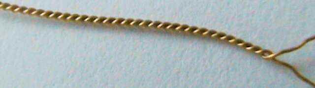
1)
We take some thin soft wire (inclosed
in rigid elastic) in varnish isolation in diameter of 0.1-0.12 mm. Varnish
isolation it is chosen plastic, light tones. Such what in hands is pleasant for
holding.
2)
We Find a place (corridor)
where it is possible to stretch a wire for the length 5-15 metres.
3)
On the one hand a corridor it is clung a soft long
spring (for tension stabilization of wound a twisted strip). To a spring the
wire hook is clung.
4)
To a hook we tie the end of a wire and we pull it in
other end of a corridor. We pass it in a wire loop (diameter of a wire of
0.3-0.5 mm), fixed in a grip of the small electric motor, and we pull a wire
back to a spring, tie it to a spring hook.
5)
Thus, moving the electric motor we can change a wire
tension. And as the wire is combined by a loop half-and-half the tension in its
both halves is levelled.
6)
At twisting of a twisted strip, a
place of fastening of a wire loop have the big loading and can easily
break. For loading easing on the loop ends we intertwine with a wire of the
same diameter for the length in 3-5 centimeter.
7)
Switch on the electric motor with a grip,
we twist wires in a twisted strip. It is not necessary aspires to set the big
turns to a motor as on the big turns it is possible to tear quickly a twisted
strip (and if to use an electro drill it besides heavy and to trace a tension
more difficultly).
8)
The twisted strip is twist until then while coils will
not rise under 30-45 degrees to a twisted strip axis.
9)
Upon termination of twisting, keeping a plait tension,
we take up it on the coil. Here the main thing not to give a weak point,
differently a twisted strip it will quickly be braided in loops and will
untangle them not simply. For reduction of this problem, after the termination
twisting, it is possible to give for some time a backspacing to the electric
motor.
10)
Now it is possible to relax.
Now actually
Converter manufacturing.
1)
The Turned out a twisted strip it is possible to reel
up the single-layered coil, for example, on a cardboard glass, and then to
impregnate this coil with rosin dissolved in spirit. Naturally, the twisted
strip ends are necessary for fixing that the coil was not unwound. On the same
glass it is possible to paste textolitea lath with
four contact platforms to which to solder four ends of a twisted strip.
2)
From a contact lath to make tap of four conductor a
cable (for example, telephone).
3)
We take two cheap the charging unit for players and
cellular telephones (see BP1 and BP2 Fig.2). We estimate what voltage to
provide in wires of our plait a current to 150 mA (on one power unit on one
shoulder of a plait) is necessary. If it is enough voltage, we put tuning
resistors (R2 and R3 on Fig.2) for current adjustment in shoulders. If it is
not enough voltage, in power units it is changed in stabilizers stabilitrons for necessary face value.
4)
Usually, in cheap the charging unit
, in the network rectifier there is one diode (D1 and D2 on Fig.2). In
one of BP we rearrange the diode in other shoulder of the condenser of the
network filter and it is connected BP to a network plug so the rectifier diodes
and filter condensers have formed a voltage doubler
(D1, C1 and D2, C2 on Fig.2). So we
will receive voltage of 560-600 V.
5)
Having taken advantage of the varistor
on 350V (R7 on Fig.2) and setting a current of stabilisation
by the resistor we will receive voltage of an order 330V (R6 on Fig.2).
6)
The Minus of the received voltage is connected on a target
chain of one BP through the resistor by 0.6-1 Mom (that the experimenter has
not knocked a current), and plus on a target chain of the second BP through the
similar resistor. (R4
and R5 on Fig.2).
7)
Now it is necessary to connect BP so that in wires of
a plait we had a counter current. And voltage between coils was an order 330V.
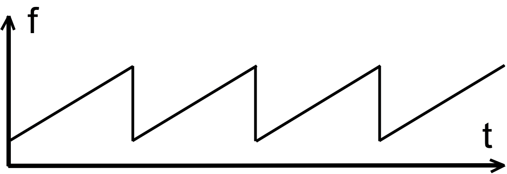
For increase in efficiency of
generation DSS cluster, and flew for comfortable perception their person,
seemingly, for field DSS of elements the high-frequency heating is necessary. Heating in a wide strip of frequencies. For this purpose, it
is possible to use generators of shaking frequency with, for example, serrated
smoothly increasing frequency of fluctuations from a minimum to a maximum, with
the subsequent sharp transition again to the low (see Fig.1). On idea, such
variant should stimulate transition of spin conditions electrons and kernels of
atoms (DSS elements) on higher power level.
|
Fig.1 |
The electric capacity between wires
in a twisted strip will be enough big (a little nan farads).
Be required the big power for high-frequency modulation of voltage between
conductors. Therefore it is necessary to be guided by modulation of currents in
a twisted strip. That is realised in Converter -RF, the electric which basic scheme is
shown on Fig.2
|
Fig.2 |
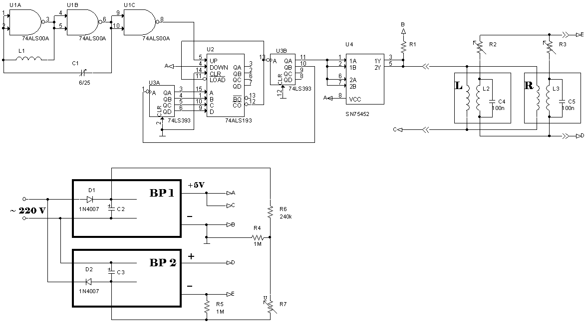
Where:
L1 - Inductance in 6 microhenry for average frequency of
generation 25 MHz,
L2 and L3 – a
twisted strip left and right twisting.
Contacts A of power unit
BP1 incorporates to contact of 14 chips U1, U2, with contact of 16 chips U3.
Contacts B of power unit BP1
incorporates to contact of 7 chips U1, U2, with contact of 8 chips U3, to
contact of 4 chips U4.
Contacts C, B power unit BP1 and D,
E power unit BP2 provide a food of a twisted strip L and R. If in 5 Volt it is
not enough that BP1 and BP2 get out on the necessary voltage, and for a food of
chips the separate power unit is used.
The scheme as follows works:
The
generator on microcircuit U1 provides frequency of a signal to 30 MHz. On this signal
binary counter U3 considers before its overflow. Then on an impulse from exit
CO parallel record of a binary code from counter U2A is made. The more its
value, the occurs overflow of counter U3 and the
subsequent parallel record faster. The overflow signal also on input counter
U2B arrives. From exit QA (with division factor - 2) impulses with porosity 2
move on an input of chips U4 (the power amplifier) which switches a current in a twisted strip L2,
L3. From exit QB of chips U2B (with division factor - 4) the signal moves on an
input of chips U2A. With each impulse its target value accrues, speed of
overflow of counter U3 increases, frequency of modulation of
a current increases in a twisted strip. There will be no yet an overflow and dump in
0 counters U2A then frequency will start to accrue again, since the minimum.
Thanks to counter U2B the step of one frequency keeps two periods. In total steps
of frequency - 16.
|
If you wish to make
the experiments, but are at a loss in independent manufacturing of the
Converter, you can order its manufacturing. Information
on E-mail: alexandrshpilman78@gmail.com |