Alexandr A.Shpilman ( sah@nursat.kz )
Modulation Detector of "Axion (Spin) Field"
(project)
For
detecting "axion fields" it is possible to take advantage of prospective inductive ability
of a field of type 3 (see Physical
properties of axion (spin) fields ), modulating its variable magnetic
vector potential.
For
modulation "axion fields" it is offered to use two E-type
ferrite cores (E1, E3)
with coils L1 and L3, reeled up as shown in Fig.1. This device contains a
circuit which provides an alternating current which causes the varying magnetic
fields of the coils L1.1 and L1.2 (including L3.1 and L3.2) to be summarized in
the central branch of the core as shown in Fig. 2.
The
detecting transformer, coils L2.1 and L2.2 (see Fig.3), is included in a
constant current circuit, so that a magnetic ring forms on the periphery of the
E-type ferrite core, E2 (see Fig.4). And the magnetic field in the central
branch remains equal to zero.
|
|
|
|
|
|
Fig.1 |
Fig.2 |
Fig.3 |
Fig.4 |
In the offered project of the detector, the detecting
transformer E2 settles down between modulating "axion fields"
cores E1 and E3 (see Fig.5).
|
Fig.5 |
The electret
screen S locks a beam
"axion fields" (it is shown by yellow color on Fig.6) generator G
increasing its density in the detector.
|
Fig.6 |
The variable electric current in
coils L1 and L3 creates in windows of E-type ferrite cores (E1, E3) variable
magnetic vector potential which switches a stream "axion fields" by
turns through the top (see. Fig. 7) and the bottom windows (see Fig.8).
|
Fig.7 |
|
Fig.8 |
This
stream, crossing the central branch of core E2, should excite in it a magnetic
field and accordingly EMF an induction of an opposite orientation in coils L2.1 and L2.2, to measure
which it will be possible in their "average" point of connection, on
contact F (see Fig.3 and Fig.5).
In the offered variant of the
project of the detector, on idea, it will be easiest to tuning out from noise
and it is possible to apply the standard electronics used in radio receivers.
In
the described design two interesting moments should be shown:
1)
Coils "axion fields" can be similar to usual coils of an electric wire. At change of
currents in modulating coils L1, L3 the longitudinal moment of a pulse of coils
"axion fields" will change that can to cause occurrence EMF in coils L2 of the detector.
2)
Passage of coils "axion fields" through core E2 will occur to delay relatively their passage
through cores E1, E3.
Combination
of these two moments, at the definite modulating frequency can induce EMF the double
frequency in the detector. That considerably facilitates struggle against
internal electric noise of the device.
At
the further improvement of a design it is possible to pay attention, that only
half of volume of coils "axion fields" is inside the detector, and other part is outside. Cooperates
with the case and other constructive elements of the device. Therefore it is
reasonable "to double" the detector, having chosen quadrupole a
variant of ferrite cores.
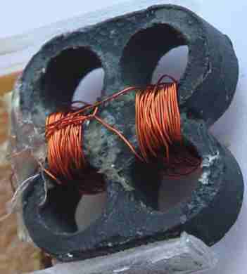
On Fig.9 the ferrite core with four windows is
shown. Two electric coils are connected consistently so, that at connection of
their connection A and B to a source of a direct current in the core the magnetic field as shown
in Fig.10 (lines by dark blue color) is induced. At such orientation of a
magnetic field, coils "axion fields" (the cut is shown by circles of yellow color) leave the left two
windows of the core and dive back into the right windows.
|
|
|
|
|
|
Fig.9 |
Fig.10 |
Fig.11 |
Fig.12 |
On an average point of two coils C relatively the pinouts A and B the variable voltage of such
amplitude moves, that the magnetic stream is switched as is shown on Fig.11 and
Fig.12. Thus coils "axion fields" concentrate that only in two top windows (Fig.11), or only in two
bottom (Fig.12).
|
|
Such two modulating cores settle down as well
as core E1 and E3 on Fig.5. The core and coils of the
detector are carried out identically by the first, orientation of a magnetic
field as on Fig. 10 and settles down as well as E2 on Fig.5. Unique difference that the
useful signal induced by change of the longitudinal moment of a pulse is
removed from an average point of two coils C "axion fields"
and by moving of its coils to the next windows (in an ideal - the signal of the
double frequency).
Apparently,
the interturn capacity of coils of the detector will play an essential role in
sensitivity of the device. In a case if working frequencies are beforehand
known it is possible to bypass this problem having connected in parallel coils
the electric condenser and having adjusted the turned out electric oscillatory
contour in a resonance with a useful signal. In a research variant, at many
unknown parameters, probably, the preliminary amplifier of a useful signal with
small entrance resistance is meaningful to use.
There is one more problem, in ferrite usually
there are residual magnetic fields which will interfere with moving of coils
"axion fields" from one window of the core in another if the size of the
longitudinal moment of a pulse "axion fields" is insufficient. This
feature can be used in the detector for measurement of the longitudinal moment
of a pulse "axion fields" setting slowly varying electric current of the sawtooth
form (from an external source) through a pinouts of an average point of coils C, and tracing the moments of occurrence and
disappearance of a useful signal.
In
addition, it is probably desirable, on a conclusion of an average point of coils
C to submit a high-frequency current dc magnetic
biasing for align characteristics
of ferrite (just as it is done in tape tape recorders).
|
Fig.13 |
At deenergizing an external source "axion
fields" inside the detector it will not disappear completely. There will
be an induced field. For "deleting" the last it is offered to capture
a design from ferrite cores external electric coil Lc (see Fig.13).
Strong which pulse magnetic field will be called force
out coils "axion
fields" from ferrite cores of the detector.